
Skarn
-
Posts
70 -
Joined
-
Last visited
Content Type
Profiles
Forums
Servers
Downloads
Gallery
Everything posted by Skarn
-
Hello, Model-Changing Network. In this article I am going to speak about my thoughts on the way level design should work in World of Warcraft, so it may come handy for those who want to create custom zones. This is not going to be a how-to or step by step tutorial. That's more like an overview of basic steps, principles, tricks and many other things that I suspect Blizzard using in creation of their content. Opinions expressed here are entirely my own and may come not quite correct in reality, as I am not a professional level designer. Though, anyway that's what I think to be correct and from my own experience it works out pretty well. Zone concept The first thing that any zone requires for sure is the concept. You can't just create a random zone that has no purpose and idea behind it and expect it to look great. I am more than sure that random creations should not serve any purposes other than tests. And even tests actually have a little idea behind such as testing a new terrain style, testing tools or testing your own capabilities. Atmosphere and general story I think that atmosphere and basic storyline are those two parts you should start designing your zone with. They should actually be developed simultaneously while you are thinking your concept over. The first thing you need to decide is what for you are creating a zone. Think a little of the events that you are going to add there. Don't try to come up with a detailed storyline and try to avoid making up characters that are going to participate in the questline of the zone. That's always too much for the first step. Just decide what race this zone will be dedicated to, what kind of major event is going to take place there (to say, is it gonna be a battlefield, a peaceful forest or a creepy dark canyon full of spiders). After this part, comes the atmoshpere. Imagine the places you want to build there. Think of the overall atmosphere things like texture color scheme, possible doodads, lighting and so on. Just get an imaginary picture of how the entire thing should look like. When you are done coming up with atmosphere ideas you can start thinking of somme particular places of interest, questing spots and other little things that you may want to havve in your zone. It is actually required for the next step of concept designing which is related to drawing a quick sketch of your zone. Anyway, if you have any particular atmosphere ideas about these places you can either think of them now or later during the actual zone development. Map sketch As I said previously, this step presupposes making of the map sketch. It is required for any zone if you want to make it look logical, natural and interesting to travel around when you are playing there. I have heard from a couple of guys that it is bad doing those "map plans" as in the end your zone simply turns out different from how you planned it to look like. Well, yes, they are kind of right as in the process of development you are trying to adjust your ideas and imaginary images from your mind to the capabilities of the game engine which is not always possible. That's quite normal and happens all the time, but you can change your plan any time, right? Most game developers do it, Blizzard devs do it and so we should. Here is the image of that kind shown by Blizzard designers in the Arcraft series (I highly recommend you to read them as they contain quite a lot of design information and describe some parts of the zone creation process. Yet, they are far from being detailed enough to teach you doing something from scratch.) As you can see on the picture, the map contains all the significant places such as towns, camps, dungeons, questing spots and so on. Different colors indicate different terrain height (usual cartography rules for doing that are quite well known: ranges from dark green to dark brown). The problem here is that this map again contains half of the information that is required for designing the zone from scratch. Blizzard is a big company and the work in designing a zone is divided by many people. As we are modders and sadly do not usually own enough of the human resources to separate the work, we most often have to do everything or our own or sharing the work with only a couple of people. Thus, you also need to think about how the player interacts with the zone, the way he goes through the the questing chains. This is usually the infromation you base the road and places of interest (POI) location on. You can draw arrows to see how the player will follow the story to avoid concentrating all the action in one part of the zone or focring player to cross the entire zone all over and over again (a little problem of classic WoW quest design, I have to admit).
-
Introduction Hello, Model Changing Network. In this tutorial I want to show you how to edit and create WMO models using Blender and happyhack's WMO scripts. Before I start I want to say thanks to happyhack for making the WMO import/export scripts and Supora for doing multiple WMO research and telling me about the tricks of WMO editing. Special thanks to Miton for the hard work on updating the script. Also thanks to everyone who however contributed to the WMO related things. Requirements Here is the list of tools that are necessary for creating WoW World Model Objects (WMO): Blender WMO import/export scripts Part 1. Installing scripts and configuring your Blender. Download and install Blender. For the current moment the latest Blender version supports the scripts. Download happyhack's scripts and place them into addons folder inside of your Blender folder. Blender\x.xx\scripts\addons\io_scene_wmo\ It should look this way. Now start your Blender and head to File -> Blender User Preferences -> Add-ons -> Import-Export and enable the WoW Wmo format (.wmo). Hit "Save User Settings". Now you are able to export and import .wmo models right from your Blender. Part 2. Basics and peculiarities of WMO editing using Blender. Those scripts are designed in quite a special way and it would probably be better to import some existing .WMO model from WoW to learn how to do things because the WMO from WoW will be already configured correctly by itself. For this purpose I am going to use a small human farm house. Before importing it you need to have all textures as .png images in the same folder as the model (subfolders are not needed, all in a plain way), otherwise the model won't have textures displayed. In this tutorial I won't explain how to model things. I will just tell you how to make them work as a .wmo in the game. I will cover the unusual parts that are different from the normal Blender usage. Materials Those scripts do not support Blender materials or texture maps. They use their own special material properties called "WoW material" which are bound to Blender materials. There you can specify the texture you apply to the model by setting a path to it and a few other less important settings: Transparent - the so-called ghost material. Makes the geometry invisible. Very useful for creating invisible walls and smooth collision for ladders. TwoSided - one-layerd geometry can be seen from both sides just like two faces facing against each other. Useful for thin things like vegetation details or ropes. Darkend - darkens the texture. Usually used on windows inside the building. NightGlow - makes the texture glowing at night, Used for windows and lanterns, mostly in outdoor groups (can still be used anywhere). There is a way to assign a texture to geometry in Blender without using materials. This won't work. So in order to assign the texture to the geometry you need to assign a usual material to it, go to material properties, find a tab called "WoW Material" and specify the needed settings there. When you assign and tweak all of them, the textures will be visible in the game. Collision In order to create collision for a model you need to go to object data while being in Edit mode, select the geometry you want collision in and assign it to the vertex group called "collision" (if it is not there create it). Then check the "WoW collision" tab in the bottom. WMO groups World of Warcraft WMO supports two group types - indoor and outdoor. Outdoor is used for exterior objects and is influenced by the zone lighting. Indoor is used for interior models, interior parts of models. It is not getting influenced by the external light. If you are planning to use indoor groups in your scene you will have to create portals for them. I will explain how to make them later. So, for setting group types, select every object one by one and set checkbox to "WMO group" and also specify a type of the group. In the same preference tab you can also see various settings: GroupName - anything you want. Useful for marking the groups, so it would be easy to find them if you ever need to have a look to the model structure, for example, in 010 editor. Please do not name as "Antiportal", internally reserved name that actually makes sense for the game. GroupDesc - Group description. Anything you want. DBC GroupID - connected with AreaID for WMO. Used to detect indoor groups for example, so server can dismount you when you enter them. Vertex shading - enables vertex color export. Use skybox - enables skybox in particular group. Skybox path is set on export. Portals Portals are used to connect indoor groups to outdoor groups or other indoor groups. If the portal is not set but indoor group is used, you will have the indoor group rendered only while standing in it, everything else will look like emptiness. A portal is a plane that contains only 4 vertices and one face (polygon, not two triangles). Portals are created as separate objects (you can see them in outliner if you import some original WMO like I did with human farm). Once the object is selected you can set a checkbox in "Object data" tab to enable portal settings and mark the object as a portal. Make sure that portal does not have "WoW collsion" and "WoW WMO group" checkboxes enabled, we need only "WoW Portal Plane". Here you see two options: "First GroupID" and "Second GroupID" which are parent and child WMO groups. They can be indoor-indoor or outdoor-indoor. Which one comes first is not really important apparently. There is no need to create portals between two outdoor groups, but I guess you can do that too. Those ids are the number of the required group in the outliner list. It is easy to find when you are working with a freshly imported original model. Though, in process of modelling those object names get messed up. In order to free yourself from calculating the number of the object manually by counting them, just export the scene and import it back. All the groups will be renamed properly. If the portal is bugged ingame, use checkbox "Invert direction". For most cases the script detect direction automatically but in some rare cases you need to invert it. Just do for the bugged ones after checking the WMO ingame. Creating custom portal geometry There is nothing complicated in making custom portal geometry. Though remember that it should be precisely on the edges that connected groups share. So, for this door it will be this place (I painted two groups indoor and outdoor in two different colors for visual purposes): If you move the portal from that point it will be bugged in game on camera rotation. Be careful with that. So, in order to create a correct plane for a custom portal select one of the groups. Simply select 4 corner vertices and press "F". It will generate a plain between them. Then select this plane and press "P". In the opened menu choose "By selection". It will detach the plane to a separate object, so you can fill in the settings. Vertex color You can paint vertex colors on WMO groups. It is used for lighting particular places of a group. For doing that switch to "Vertex paint" mode. You can learn it by practice or by using some Blender tutorials or documentation. Though, I will tell you two important things about it. You can paint colors and you can fill everything with colors. For filling, pick up a color and press "Shift + K". Indoor groups should always have vertex color, else the game crashes. So make sure that "Vertex shading" checkbox in "WoW WMO group" settings is enabled. If you group (either indoor or outdoor) has no vertex color data, but you set a check box, the model will be pitch black in the game. Be careful about it. Export There are some export settings to be observed when you are ready to see your awesome model in the game: Operator presets - allows you to store "favorite" export settings for WMOs. Use ambient - enables ambient lighting (indoor groups). The ambient color is defined below. Fill water - makes you WMO fully filled with water. Useful for underground caves. Note that exterior parts will be "sunken" too. Save source doodads - preserves the m2 doodadset that was imported along with the model. Save source fog - preserver fog settings imported with WMO. Thanks for reading! This tutorial is relevant to the recent version of WMO import/export scripts for Blender. If the script gets updated, the tutorial will be updated too.
-
Introduction Difficulty: Relatively easy Estimated time: 30 min - 1.5 h. Requires: Adobe Photoshop, MapTemplate.psd. Here is the example map that I am going to use as an example for the tutorial. The shape of the continent belongs to one Russian Minecraft project (Medieval Minecraft) and represents their world Asteros. I was too lazy to make something up on my own, so I decided to take this shape. I made this map in about one hour using a graphic tablet (can be also done without it), so it is not that complicated as it may look like. I created a new version of MapTemplate.psd based on the old one by Soldan and using the new WoW worldmap assets provided by Vellear. So, let's begin! Creation process Step 1. Getting the shape. Launch your Photoshop and open MapTemplate.psd. Choose the Ocean layer you prefer and make it visible (it may be with or without watermarks, I used the one without watermarks). Select the ground layer without making it visible. Now use the Lasso Tool (L) to paint the shape of your continent. You can also do it in many other ways, but the main point is to get a properly shaped selection on your canvas. Now switch to Rectangular Marquee Tool (M) and right-click somewhere on the selected space. In the context menu choose "Layer Via Copy". Now you will get the continent shape displayed on a new layer. It may look a little unsatisfactory (such as having a lot of rubbish around, weird shapes and so on), so you can clean it and master the shape using Eraser tool (E). Here is what I got after cleaning and working on the shape: Step 2. Adding details. Now pic up small radius hard brush and use Eraser Tool to paint small rivers, lakes and other details involving the landscape. It is important to use hard brush because soft ones make bigger borders around themselves, so it does not look that good. For this task graphic tablet with pressure sensivity saves tons of time. Here is the result: Now it is time to add some mountains to your continent. Select the layer with the mountain pattern and scale it to fit the size of your continent. You can reduce layer trasparency to see the continent shape through it, so you can decide the average size of the mountains. Switch back to your continent layer and right click on it, choose "Select pixels". This will select your continent again. Get back to the mountain layer and press "Ctrl + Shift + I" in order to reverse the selection. Press delete. Now you have your continent entirely filled with mountains pattern. Use soft brush and Eraser Tool to get rid of the unnecessary mountains and blend them with the ground. You can also make a copy of the original mountain pattern and cut some bigger mountains from there. Be creative to make something interesting. Here is what I got very quickly. Let's finish the shore lines now when the mountains are done. Switch to your continent layer and select its pixels. Go to Selection - Modify - Expand and enter some value like 10 or 12. The space between expanded selection and your continent is going to be your shoreline (water shelf). It should look somewhat this way: Choose the Coast Line layer, select Rectangular Marquee Tool, right-click on selection and choose "Layer Via Copy" in the context menu. Now you will have your shore lines, though they would not look blizzlike. In order to fix that we need to change layer blending settings. So, double click on the little icon representing the layer in the layer manager. Set a check box to "Inner Glow" and choose the appropriate color. Now it is time to get some decorative lines, representing the sea waves or whatever Blizzard thinks they do. They really add much style to the map. Make the Sea Lines layer visible, select continent pixels, get back to lines layer and press "Delete". Now remove the unnecessary lines all over your map using soft brush and Eraser Tool. You can also slightly increase the opacity of the layer as the default one is not on max. It will get more of a Blizzlike feeling. Step 3. Coloring the map. This is basically all you need to do to get a Blizzlike continent. Though, as we are modders, we should improve something, not simply replicate what Blizzard do to their continents. Let's make the map more interesting by coloring different climate zones or something like that. In general, let's go from the boring parchment color theme to something more colorful. Make a backup of the continent and mountain layers. Set the brush mode to "Overlay". Now use soft brush and Brush Tool (B) to paint colors on the ground. Then do the same with the mountains if necessary. That's all. Don't hesitate to leave feedback about my tutorial in the comments
-
IntroductionDifficulty: Hard This tutorial is dedicated to explaining the basics of scripting in SweetScape 010 Editor. First of all, I want to say that I am not a programmer and the way I write the code may look weird to a person who knows more about programming. But following my way you can create useful script to automate many tasks you need to perform with World of Warcraft files. Important: You don't need any programming knowledge to start learning scripting in 010. I did not have any at first at all, so we are going to start from the real basics. 010 Editor uses two different filetypes to perform operations on the file. The first one is template (.bt) - it parses the file and gives us the structure with which we can work manually or within a script. Templates for most WoW files are already written and I am not going to teach you making them as I don't have that much of that knowledge myself. The next one is script (.1s) - scripts can be executed inside 010 editor, but unlike to templates, they can be excuted both on an open file or in a plain way (without a file opened). 010 Editor scripting uses a C-similar language. For experienced users: The language (1SC) used in 010 Editor scripting is indeed similar to C and shares most of the functions and syntax with it. Though, some parts of it are really weird and different from the the original C. Some functionality of C is not implemented. So, be careful and read the function reference. Learning basicsThis page contains a lot of useful information about this hex editor, though we are mostly interested in Function Reference part. Let's have a look at it. It contains a description of how you can use each available function. This is vitally important to read those definitions if you want to learn scripting. IO Functions are functions that take and return a value. They are used for most of our data operations including reading, writing and so on. Interface functions allow you to emulate the actions of a user such inside the editor, such as closing or saving the file, opening files, moving cursor and so on. Math functions are obviously doing some mathematical calculations. I have not used functions from other pages but I guess they can be useful too. So, the basic idea is to execute a template on a file, get the structure and read or write some values to it. Writing your first scriptSo, when I was learning 010 editor scripting what I started from was pure practice. Just trial and error method, no programming knowledge at all (I did not even have programming at school, as most people do). And I suggest you doing exactly the same thing because it is easier to learn by making something useful rather than reading boring theory written by some noob who obviously codes wrong in a non-professional way, but yet working. The first thing that we are going to do is a collision cloner script. The purpose of it is to copy collision from one .m2 model to another. Some of you may ask: "What's the use of it? Let's make something really useful!". Well, basically when you create custom models, sometimes you need to have some parts of model collidable and some not. The convertion software always sets collision to the entire model, which is not what we want. So we can create two version of a tree - with leaves and without leaves. Then we convert both to .m2 model and copy collision from the one without leaves to the one with leaves. So, we get a collideable trunk and leaves that you can pass through. Anyway, let's get started. Step 1. Investigating the dataFirst of all, when we know what we want to do we need to find out what data is reponsible for handling collision. The best source of information for that kind of things is our Wiki (the link is in the upper menu of the website). But in case of collision, everything is rather simple. So, first thing that I want you to do is to create an empty script file and open some .m2 model in 010 Editor. Apply the M2Template1.bt script on it. We get a dropdown with the structure: This is a shortened version because the list is too long to display. M2 file structure is based on offsets (starts with ofs). Those are values that are always located by the same adress no matter what model it is. They identify the adress of an actual block of data in the file. So, you can just read them and know where the actual data is written. The lines starting with (n) identify the amount of elements used in the data array. They are also static and are always located on the same adress. And everything else is structures. The client finds out how to read the file by reading ofs's and n's and finding out where the block of data is located in the file. There is no matter what the order of the data structure is when the static part is over. So, what we are going to do is: Read offsets for collision.Read the amount of data elements.Find and read the collision data depending on the given values.Copy it to the end of the target file.Change offsets and n-values to the proper values corresponding to the new data.The old data block will remain the file, but the client won't read that part as offsets won't point to that adress anymore. The last thing you need to do in this step is: Right click on the structure - Coloumn Display Format - Name. It will save you a lot of time in the future steps, just believe me. Step 2. Writing the scriptI will paste here the entire script and write comments to it explaining how things work. So, by reading attentively this script and trying to understand what it does you can learn the basics of scripting. Basically, it covers most operations that we need to perform on WoW files. Let's also look into some other useful things now. Useful patternsHere I will provide a set of code snippets that can be used for constructing your script in no time, not depending on the purpose of it. I will post plain code here and explain what each of them does and how it is better to use it. Snippet 1. Batch file processing.One of the most useful things in 010 editor scripting. It allows you to execute your script on multiple files at once. There are quite a few ways to do it such as CMD execution, but we will talk about that a bit later. Example script. Sets the MFBO chunk of an .adt to a given values: CMD ProcessingYou can also do perfectly without this snippet by using CMD way of execution. It has a lot of advantages comparing to what I just wrote. Though, ,y snippet allows you to select multiple files no matter what they are. You manually select what you want to do processing on from the folder. CMD way is very automatic and only works on a particular file extension. Create a script file that contains only processing, no InputOpenFileName and so on. Just plain processing. Create a .cmd text file containing this: Now you can save it an launch from the folder. You can also change the arguments. @ECHO OFF disables the CMD black window. /r enables processing in all the subfolders. for %%x in (*WMO) do 010editor "%%x" -script:"C:\Users\Skarn\Desktop\wmo-converter.1sc" executes the script on all the .WMO files. -nowarnings disables the warning window. -noui allows you to execute the script in a noui silent way, so you can process thousands of files and blinking windows won't bother you. Snippet 2. Coming soon!
-
Ground effects, music and additional things THIS TUTORIAL IS UNDER CONSTRUCTION Part 1. Ground effects Ground effects is the essential thing for most maps to make them look complete. They are basically small autoplaced doodads (models) that are bound to a certain texture in an .adt file. Most often they are used for creating grass, small shrubs, stones and other clutter on the ground. In this tutorial we will learn how to add existing ground doodad sets to your maps and how to create new ones. Step 1. Creating a new ground effects set Basically, every ground effects set consists of 4 detail doodad models and a bunch of various setting configuring their appearance in the game. They are stored in "World/NoDXT/Detail/" folder of your client and can be viewed in WoWModelViewer. So, pick up any 4 models that work well together and write down their file names somewhere. Those are the ones I picked up: elwgra01.m2 elwgra02.m2 elwgra03.m2 elwflo01.m2 Now we need to find the model ID for each model in GroundEffectDoodad.dbc. If the model is not listed there, we will have to add it. Open "MyDBCEditor" in "Tools" folder of WoWDevKit. Open GroundEffectDoodad.dbc Search for "elwgra01" and write down the number of the string which is going to be our ID. If the search function does not find anything, you need to add a new line to the end of the table. So, for me it is: elwgra01.mdl is 4 elwgra02.mdl is 5 elwgra03.mdl is 6 elwflo01.mdl is 1 Now open the GroundEffectTexture.dbc, go to the end of the file and create a new string. Write down its ID somewhere, we will need it later. Fill the string with your data according to the following pattern: Coloumns 2-5 (red) stand for model IDs we figured out before. Coloumns 6-9 (blue) define the amount of time each paticular doodad appears in a group. Coloumn 10 (green) controls the groundeffect density of this group. In most cases 24 is an optinal value, but you can actually experiment with some values like 0, 1, 2, 4, 8, 16, 24, 48, 128. Though, after 24 doodads show up in a kind of weird way. Coloumn 11 links to TerrainType.dbc which control different additional effects like footstep sound, dust or snow particles appearing while walking and so on. Step 2. Injecting ground effect data. Make a backup of your map files and copy the ADTs to the following folder: "WoWDevKit\Tools\CMD\GroundEffects\". Launch "groundeffects.bat". You will see the following CMD windows which pops up for every .ADT located in that folder. It asks you for groundeffects ID you want to apply for each texture that the ADT contains. So, apply the ID of the set we created to your grass texture, for example. In order to skip the texture type in "-1" and press "Enter". Type in "0" if you don't need any set applied at all. Run the "groundeffects_fix.bat" in the same folder after you are done with the previous step. Move the new files to your patch or working directory. Part 2. AreaID. AreaIDs are basically DBC string values that get written to the chunks of an .ADT and are resposible for showing up the zone name in the game and some other zone related things. So we are going to learn how to both create a new AreaID entry and how to assign it to your map as well. Step 1. Creating a new AreaID entry. Extract the latest "AreaTable.dbc" from the latest locale patch and open it with MyDBCEditor. Create a new empty line in the end of the file and write down its ID. Write in your MapID from Map.dbc into the coloumn number 2. Coloumn 3 is a link to the parent area. For example, if your newly created area is located in Kalimdor it should link to the AreaID of Kalimdor in this same table. Coloumn 4 should better stay as any unique number but not bigger than 4500. Coloumn 5 contains different flags which are explained on our wiki. Coloumns 6-10 stand for various music settings we are going to talk later. Coloumn 11 defines the zone level. (Level of a character required for the zone being explored). Coloumn 12 contains the name that shows up in the game. Everything else is not necessary to know at first, but you can read about it on our wiki. Step 2. Assigning AreaID to your map. AreaIDs can be painted with Noggit. In order to do that. Switch to the AreaID painter mode by selecting it on the toolbar or pressing "5" on your keyboard. Press "X" in order to reveal the AreaID selector. Now you will see a windows full of different entries. Those are all AreaIDs that exist in the game and are currently loaded by Noggit. Select any AreaID and paint it on the ground by holding "Shift + LMB". Save the work and go in game to test it. Part 3. Music The picture below shows the connections between the DBC we will have to edit in order to assign music to a zone. Open all those DBCs (AreaTable.dbc, SoundAmbience.dbc, ZoneMusic.dbc, ZoneIntroMusicTable.dbc, SoundEntries.dbc) in MyDBCEditor or an other editor you prefer to edit DBC tables with. In order to add any type of music to your zone, the AreaID to which you assign the music should be "painted" on .ADTs as well. Otherwise, your changes won't affect anything. Ambience At first we will learn how to add ambience to a zone. Go to "SoundEntries.dbc" Go to the end of the table and memorize the ID of the last string. Right click on any line and select "Copy line to" in the dropdown menu. Enter the new string ID (last used ID + 1). Do it twice (create two new strings for day and night ambience). Do steps #4 - #14 for both day and night entries. Change the value of coloumn #2 in both string to "50" which stand for the ambience sound type. In coloumn #3 enter any description of your sound you want. In coloumn #4 you should enter the name of your sound file with an extension (e.g. "MyAwesomeTrack.mp3"). No path here! Only the file name. Coloumns #5 - #13 can stay empty for now but you can read about their usage in our wiki. Coloumns #14 - #23 should contain the value "1". In coloumn #24 we enter the folder path to your music file (e.g. Sound\Ambience\Custom). You should not have a backslash (\) in the end of the value! Coloumn #25 controls the sound volume. Most ambience sounds are set to "0.69" by default. Coloumn #26 is responsible for sound flags. Set it to "0" for now, but you can read the information about them on the wiki. Coloumn #27 defines the minimum sound distance. In most cases Blizzard use "8.0" value. Coloumn #28 defines the maximum sound distance. In most cases Blizzard use "45.0" value. Coloumn #29 adds EAX for the sound reflection and realistic feeling. Set it to "0" for now. Coloumn #30 should stay as "0". Write down the IDs of both strings and save the table. Switch to "SoundAmbience.dbc" Create a new string in the end of the file. Write down its ID somewhere. Fill in the day ambience ID from SoundEntries.dbc to coloumn #2. Fill in the night ambience ID from SoundEntries.dbc to coloumn #3. Write down the ID of the string and save the table. Switch to "AreaTable.dbc" Find your AreaID string and fill in the SoundAmbienceID into coloumn #8. Save the table. Music Go to "SoundEntries.dbc". Create two strings for day and night as we did with ambience. Everything works exactly the same except for some differences that I will list below. Coloumn #2 should contain the value "28" which stand for the "BackgroundMusic" soundtype. Coloumn #24 is responsible for the volume. Mostly Blizzard uses "0.6" for music entries. Coloumn #28 should be set to "2". Switch to "ZoneMusic.dbc". Create a new string. In coloumn #2 enter any name you would like and understand. Set coloumns #3 and #4 to "180000", coloumns #5 and #6 to "300000". Enter the ID from "SoundEntries.dbc" for the day music. Enter the ID from "SoundEntries.dbc" for the night music. Switch to "AreaTable.dbc". Find your AreaID string and fill in the ZoneMusicID into coloumn #9. Save the table. ZoneIntroMusic Open "SoundEntries.dbc". Make only one string for the intro music using the same settings as for zone music we assigned in the previous step. Switch to "ZoneIntroMusic.dbc". Create new string. Type in any name into coloumn #2. Type in the SoundEntriesID to coloumn #3. Type in the value "1" into coloumn #4 Type in the value "60" into coloumn #4. Save the table and write down the ID of the string. Switch to "AreaTable.dbc". Find your AreaID string and fill in the ZoneIntroMusicID into coloumn #10. Save the table.
-
Alphamapping Tutorial THIS TUTORIAL IS UNDER CONSTRUCTION As you have already learned in the previous part of our tutorial, World of Warcraft uses 4 layers to store the texturing data. Every layer of textures, except for the first one, is basically a usual grayscale image. So, there is a way to do texturing work a lot faster by editing those layers as a whole images. This process is known as alphamapping. You could see the result of alphamapping in the previous parts of our tutorial when you worked with our tutorial map. For using and learning alphamapping you would need a good 2D graphics editor. We recommend to use Adobe Photoshop CS6, but you can also use Gimp. The process will be explained using Photoshop, so some parts and functions may be different in your editor. Download our PSD alphamap demo Before you start creating your first alphamap, you should think about organizing the layers properly. As we are limited to 4 textures per chunk, you should decide what you are going to place on every layer of your alphamap. As you can see in the PSD demo above, Blizzard developers are not very organized with their layers, and it will only make things more complicated for you in the future. Now I’ll quickly explain my own system. First layer (the one you cannot edit) is always dirt for me, the second one is rock, then goes grass and the last one is darker/lighter grass. As you see, all 4 slots are already used, but sometimes you need to make a road or whatever you want. Most people just avoid using the dark/lighter grass layer which obviously makes your final zones look way worse. The solution is actually really simple: you just need to place your road on the same layer on the rock layer where there are no actual rocks around, so you’d be able to swap it to whatever you want. So, now when you’ve got the basic understanding of how texturing works, you can try creating your first alphamap. Step 1. Preparing your working space. Every ADT files basically contains 3 grayscale 1024*1024 pixels .png images which we will need to edit for creating alphamapped texturing. It is not convenient to edit all your .ADTs one by one, so we are going to create a single image for the entire map. Start your Photoshop. Go to “File” and select “New…”. Enter any name you like. Fill in width and height depending on the amount of .ADTs you have on your map. Just count how much .ADTs your map has in width and height and multiply each value by 1024. As an example I took a 5 x 5 map. So, 5 x 1024 = 5120. Press “Okay”. As a result you will see a white space. Pick up the “Paint Bucket Tool” and fill the area with black color. Now you need to divide your image into slices which represent every .adt file in your map. In order to do that, first go to “View”, choose “Show” and enable “Slice”. Also make sure “Extras” is also activated. Then find a “Crop tool” icon on the toolbar, right click on it and select “Slice tool” in the dropdown. Select the whole area with it, right click somewhere and select “Divide Slice…”. You will see the following window. Now right click on every slice and select “Edit slice options” and change the name of every slice to its coordinates on the ADT grid. It is boring, but it will save you a lot more time in the future. Step 2. Creating the alphamap Open the following folder: “WoWDevKit/Tools/Futa/Templates/”. Import some mountain templates from that folder in Photoshop and make a desired landscape layout out of them. You can copy, rotate and paste the same piece of template as much as you want. But don’t be repetitive in order to create a better map. Also try to avoid resizing mountains, especially making them bigger. It will make the texturing look blur in the game. So, here is an example landscape: I also recommend to create a separate layer and fill every ADT there with “chunks.png” that is provided in the “Templates” folder. It will help you to organise chunks properly when you need to create a road or something else that requires additional texture. Now create two additional layers out of dark grass and light grass templates. Switch back to your mountains layer, right click on it and press “Select pixels”. Switch back to one of the grass ones. Press “Delete”. Hide the revealed mountain layer. This is how it should look like: Do the exact same thing for the second grass layer (exclude mountains pixel from it). Export each layer + black background using the “Save for Web” function which can be found in the “File” menu. Select all the slices of your image in the windows where they are displayed. Set the extension to .PNG using the dropdown menu. Click Save and save your images to the “FuTa” folder of WoWDevKit. Step 3. Injecting alphamaps. Make a backup of your map files and open them in “FuTa.exe”. Keep in mind that you can only edited fully textured files with FuTa. It means that all 256 chunks should be filled with 4 textures. Open “Settings”, “Alphamap”, “Format” and set it to grayscale. Open every .ADT one by one and import your layers corresponding to the adt coordinate numbers. It is a long and boring process but you have to deal with it. At least, it is hundreds of times faster than manual texturing. Select every .adt one by one, go to “File” and click “Save”. You should save every opened file one by one. For speeding up the process you can use arrow buttons on your keyboard for navigating faster. Add the files to the patch or your working directory. Additional part. How to rip alphamap templates from Blizzard's maps. We have provided you with a bunch of alphamapping templates within our WoWDevKit, though it may not be enough, especially if you are working on a big project with multiple zones. So, the first idea of the solution to this problem is to extract the alphamaps from original .ADTs. However, there is a small problem. Unlike to Noggit, WoWEdit (Blizzard's map editor) does not care about the order of textures it paints on the ADT chunks, so sometimes multiple layers are messed up on one ADT. Though, it can be solved using a graphic editor. So, let's do it. Step 1. Choosing the proper .ADT to export from. I recommend you searching for the .ADTs that contain as much more mountains (or any other pattern you want to rip) as possible. Rip only those alphamaps that you can later raise with Noggit. From my own experience, some mountains styles like cliffs or spikes have the hardest alphamaps to raise. So, don't waste time if you want the immediate result, those alphamaps would require quite some terraforming skill to get raised. You should also try searching for some good repetitive patterns that can help you to create long mountain ranges by just copying them around. Here is an example of Blizzard using them in Hyjal (3.3.5a version). This particular mountain pattern is already ripped an released with our WoWDevKit. Step 2. Exporting and fixing the alphamaps. Open your .ADT file with FuTa, select the alphamap tab and press Export. All your 3 layers will be exported into the folder with the map files. Let's imagine that we want to rip that mountain range template. As you can see, some chunks are missing. You can find them as 1.69 x 1.69 cm squares on the other two layers. So, go to those layers. Scroll closer to the chunk by holding "Alt" and scrolling the mouse wheel until a pixel grid shows up. Select the chunk by using the "Rectangular Marquee tool", copy it and paste it to its place on the first layer. Do it for every missing chunk.
-
Creating your own custom blank map THIS TUTORIAL IS UNDER CONSTRUCTION For this tutorial you DO NOT need Taliis or any other outdated software! Please use the software specified in the tutorial. Pictures from Taliis are just an imaginary explanation of how the WDT grid looks like. If you have read all the previous parts of our beginner’s tutorial, you are probably able to perform almost all the basic operations on World of Warcraft maps. In this part of the tutorial, you will learn how to create new blank custom map for your builds, expand it and join different maps together. First of all, you should get a basic understanding of how maps are handled in WoW client. Every map basically consists of .adt files, one .wdt file, one .wdl file and an entry in "Map.dbc". Now, we will explain what each file type is responsible for: .ADT file is the most important element of ever map’s structure. It contains heightmap, texture, model and many other kinds of information. That’s the files Noggit is mostly aimed to edit. .WDT file keeps all information about the position of every .adt file on your map, the quantity of used .adt files and some other things. Every map has only one .wdt file. .WDL contains some heightmap and model information which is used by the game client for rendering far away mountains, models. This file also also allows Noggit to display your map contours on the map preview. There is only one .wdl file per each map. This file is optional and a map will get loaded even without it. So, let’s get started and create your first custom map. Step 1. Generating .adt files First of all, you should decide on the size of your map. I will use 5 x 5 map as an example. This is basically how the .adt array in .wdt files looks like. So, now imagine that we want a map of 5 x 5 .adt files in size. Launch AdtAdder.exe tool which can be found in your WoWDevKit in the Tools folder. Select a source .adt from your ADTAdder folder. The file is named “Template_0_0.adt” Enter your map name. This is how your files will be named, it does not affect anything much. Fill in the coords that are demonstrated on the picture below. Everything is quite clearly explained there by arrows and other pointers. Press “Start creation” button and wait until the tool creates your files. Step 2. Moving your .adts and generating .wdt files Now you have your map files, but the client is not able to read them because there are still no .wdt file. In order to create it, open a tool called “Riu’s zone masher” in your “Tools” folder. Once opened, you will see this window. Click on File and choose Add files. Select and open the .adt files we generated in the previous step. Now you should have your files imported, so that you will see them as blue squares on the grid. Move this group of .adt files to the center of the grid, so you will be able to add some extra files to expand your map from every side in the future. Make sure Fix Offsets and Create WDT options are enabled. Enter the map name which will again be the name of the files. Enter your map name Press Mash! Your map files are now saved to the “Riu’s zone masher” folder. The folder will be named identically to your map name. Add this folder to your MPQ or project folder or client directory (if folder loading “WoW.exe” mod is installed) within the following path: “world\maps\”. Once one group of .adt files is loaded, you can load some more which will appear as a separate group. This is the way you can expand your map or change the shape. Step 3. Adding an entry to Map.dbc Map.dbc is located in DBFilesClient folder as well as all other .dbc files. It contains different data including the real map name, map type, etc. You can read more about it on our wiki. [LINK TO WIKI] You can take the “Map.dbc” file from our tutorial map, you have been practicing on in the previous parts of the tutorial. Or you can take it from the latest locale patch. Open it with “MyDBCEditor” which can also be found in the “Tools” folder. Go to the end of the table and see what ID is the latest. Memorize it. Select Azeroth or Kalimdor line by left clicking on it. Right click on the selected line and choose “Copy line to”. Enter a free ID here. (Last UID + 1). Rename the field “Azeroth” to your map name. The name your .adt files have. Enter the real name of your map instead of Eastern Kingdoms in your language. Click “File” and “Save”. Add your “Map.dbc” to the patch, project folder or client by the following path: “DBFilesClient\” Now you have your map working in Noggit!
-
Learning the basics of map editing in Noggit THIS TUTORIAL IS UNDER CONSTRUCTION This tutorial explains how to use most basic Noggit’s features required for worldbuilding. First of all, you need to download Noggit itself: We also prepared special map for you to practice on. Launch Noggit and open the ExteriorTest map in the Continents tab. Click on one of these squares to open the map. Orange squares represent .adt files located in your project folder, gray ones are ADTs stored in client .mpq archives and the green ones are .adts that have a corresponding .wdl file the purpose of which will be explained in further parts of the tutorial This map created special for practicing in ground modeling, texturing, model spawning, water editing and other things. If everything is okay, now you should have your map loaded and be able to start practicing. As you can see, there are different pre-textured areas for you, so you can raise them and practice your shaping (also known as terraforming) skills. You can also find some examples of mountain and texturing styles there. But before you start, let us explain how to use the different tools and modes available in Noggit. Introduction to Noggit’s graphic user interface On the left side of your screen there is tool bar with 9 icons which represent all the existing world editing modes. Here are the explanations of each one from top to bottom of the toolbar: * Raise/Lower - modifies the height of the ground Flatten/Blur - flattens or blurs the ground 3D Paint - allows you to paint textures Holes - adds or removes the holes from the ground which are necessary for caves, cellars and etc AreaID Paint - sets the area ID to the selected chunk which effects the name showed up on your screen while entering the zone Impassible Flag - marks the chunk as impassible for a player to pass, so basically - an invisible wall Water edit - allows you to perform various operations with water, such as adding it chunk by chunk, changing its height and many more Shader editor - currently unused button of a planned feature which can also be useful for us in some cases Object editor - allows you to work with the objects on your map, such as WMOs and M2s Underneath the toolbar you can see a currently selected texture for texture painter or texture swapper. The top menu contains a lot of tabs with additional functions which are responsible for rendering and editing options (“View” and “Edit”) and some additional functions (“Assist ”). There is also a “Help” tab that contains a small hotkey information note. There is also a status bar in the bottom of the working space that shows you some information about your current position on the map. All tool keyboard and mouse shortcuts can be found in a hotkey pop-up windows by pressing “H” on your keyboard. Ground Modeling As was already said, your map contains a lot of pretextured areas and mountain shaping examples you can practice ground modelling skills in. Try to look at the finished and shaped areas and reproduce them yourself by raising flat textured spaces. In order to do this you will need the first two editing modes available in Noggit. (!) Basic editing modes can be changed by pressing 1-9 buttons on your keyboard. So, select the first tool called “Raise/Lower". When selected: Hold the “Shift" key and move your mouse on the terrain. It will increase the height of the ground in your brush area. Doing the same with “Ctrl” key held will do the opposite thing - decrease the ground height. In the option windows in the upper right corner of your screen there are a set of various brushes and setting that affect the result of raising or lowering the ground. The linear brush which is also selected by default is the most important one for modelling the ground. It creates the smoothest shapes for your mountains. Other brush types are also working and used for other purposes, for example other mountain styles. You can try each one somewhere on the map to get the basic idea of what they are useful for. Now try to raise some mountains. There are some keybindings that may help you to increase the speed of your terraforming. If you hold the ALT and move your mouse, the brush radius will change without touching the UI. You have probably already noticed that at some place the ground has some spiky sharp edges. In order to remove them, use the second tool called “Flatten/Blur” by using “Shift + LMB" for flattening, and “Ctrl + LMB" for blurring. So, you can know start sculpting the mountains. Look how the finished areas are created and try to replicate the shaping style. When you get a close result, you can try to shape the mountains in your own way. Maybe you will create something better ;). By pressing F9 you can toggle the height lines on your map which are really helpful when you are modelling the ground. Texture Swapping You may expect that the next thing we are going to learn after ground modelling is texturing, but it is not. We will explain how to texture the terrain in the next parts of the tutorial series. But now you should learn swapping textures that are already painted on the map. In order to do this switch to 3D Texturing mode using the toolbar or by pressing 3 on your keyboard. Hold the “Ctrl” button and click somewhere on the ground. You should now see a “Texture picker” window which shows you the textures that are currently used on the chunk. If you press F7 on your keyboard, the map will become covered with red and green lines, You should remember that green squares show the borders of each .adt file in your map, while red squares represent chunks of this file. As you may have already noticed, one chunk can only contain 4 textures and it is essential for WoW modding to keep all 4 chunks filled, but you should not worry about it while working with the tutorial material. The reasons for doing it will be explained in the next parts of out tutorial. Press the button called “Texture Swapper” in the brush setting window in the upper right corner of your screen. Now select the texture you want to change with a texture picker. Press the “Set destination” button in the “Texture swapper” window. Now this texture is selected as a target one for swapping, so that it will be replaced. Select a texture you want to replace the target one with. In order to do this, press X on your keyboard. You should now see a “Texture palette” window. Now you may load all the available tileset textures in the game or load some from a zone you want. Press “Load all tilesets” button or load a specific set. You may sort the textures by pressing the “Filter textures” button and selecting the required parameters. Once the texture is selected, press the button “Swap ADT” in the swapper window. It will change the currently selected texture pair on one .adt you are currently on. You can also swap textures chunk by chunk by holding “Shift” and pressing left mouse button while moving it on the ground. Placing models In order to spawn models on your map you need to run WoWModelViewer and Noggit at the same time. Look up a model using a search field in WMV. When you find the model you want to spawn, switch to Noggit and press the following key combination: SHIFT + C for spawning an .m2 model; ALT + C for spawning a .wmo model. You can use the “Ctrl + C”/”Ctrl + V” keybinding for copying and pasting models. When the model is selected you are able to scale it and rotate in different directions. Hold “Shift”, “Ctrl”, “Alt” and press right, left and middle mouse buttons while moving your mouse. Practice a bit and you will get used to the rotating shortcuts. [KEY COMBINATION PICTURE] You can use SHIFT + R for resetting the model’s rotation and PageDown for setting a model to the ground level. Numpad keys can be used for moving model slowly which is helpful for correcting the position of some small models. If you hold “Shift” while pressing one of those numpad buttons, the model will move slightly faster. We also want to remind you that all the basic key binding information can always be found in a Help window in Noggit. Adding water Now it’s time to add some water to your map. Switch to “Water edit”. You can fill the entire .adt with water by going to the “Assist” menu and clicking on the “Create water” button. “Clear water” in the same menu is used for removing all the water data from the .adt. Pressing “Create water” will create a flat tile water at 0 ground level. You can change the height of the water layer by using the buttons in the setting menu in the right upper corner of your screen. It is also possible to change opacity and water type. Play around with those features to understand how they work. Now create water on the blank flat .adt. Try raising the ground and creating some kind of lake. Now, you have some water underneath your terrain. It is not good because it produces water sounds in game, and also allows fishing everywhere on the map. So, you always have to cut the unnecessary water by pressing “Crop water” on the setting panel of “Water edit”. It cuts all the extra water under the ground. Sometimes you need to have different levels of water on your map within one .adt. You can add water to the chunk by pressing “Shift + LeftMouse” and remove it with “Ctrl + LeftMouse”. You can also select chunks with “Alt + LeftMouse” and deselect them with “Alt + Ctrl + LeftMouse”. When something is selected, height control buttons affect only the selected water chunks. It works for everything except opacity generator and water type selector. Those are currently not supported in chunk by chunk editing.
-
IntroductionHello, BNet-Dev. Today I am going to show you guys how to make custom non-animated .m2 models out of .mdx (Warcraft III) models. It is believed that converting models using MDXtoM2 is quite a complicated process but actually it is not that hard. You may ask: "Why do we need to do it if we have OBJtoM2 and it works fine?" Well, the answer is simple. This converter provides you a lot more possibilities than OBJtoM2, such as multiple materials, textures, lights, animations and etc. At first, I will show you how to convert static .m2s but I am going to update this tutorial from time to time when I find out something new. Okay let's go. Tools and resourcesThe full conversion will require quite a big bunch of tools which you have to download. 1) MDXtoM2Converter_lazy - a tool that generates .m2 models out of .mdx files. 2) 3DS Max with MDX export plugin or Milkshape. Well, just something to convert your model to .mdx. If you already have your .mdx object, you don't need it. 3) MDLXConverter - a tool that converts .mdx files into .mdl files which are possible to edit manually via Notepad. 4) MDLVis - .mdx/.mdl editor. 5) War3ModelEditor- a tool that allows you to add some additional sections to .mdx, such as lights, bones etc. 6) BLPLab - for converting your textures to .blp (BLP2) file format which is undesrtandable for WoW. (Warcraft textures are BLP1 and cannot be read by WoW). 7) Collision adder - a tool that generates collision in your m2 file. 8) Resizer.py - a python script that allows you to resize the initial size of your model. 9) PyModelEditor (+Python 2.6 (see PyME thread for details)) to run Resizer.py 10) AddViewDistance for editing the render distance of the model. 11) Sweetscape 010 editor (+ M2 template) - a hex-editor which we are using for fixing bugs in the model. 12) Nullmodel.mdl - .mdl template to make your model understandable for MDLVis. Well, there are plenty of other utilities that can make your model better but they're not essential. The list is quite huge, but don't worry, it won't take that long to get your model into game. Tools which are not linked here are either included into one of the linked packages or can be found in the resource section of Modcraft. Chapter 1. Static models Step 1. Preparing your model1. I won't explain you how to make an .mdx model. There are plenty of tutorials on this theme over the internet. At first, your .mdx file does not contain all the information you need for converting it to .m2. In order to fix it you need to convert your .mdx file into .mdl using MDLXConverter. I will call the result model tree.mdl. 2. When it is done you need to open your model in MDLVis. To make MDLVis open your file you have to make the .mdl structure understandalbe for MDLVis. So, pick up Nullmodel.mdl and tree.mdl model and open them in Notepad++. Find a section called Model in your tree.mdl and add missing strings into this section from Nullmodel.mdl. * tree.mdl } Model "pine" { BlendTime 150, MinimumExtent { -261.362000, -252.451996, -88.562103 }, MaximumExtent { 273.287994, 307.015015, 1465.869995 }, BoundsRadius 796.038025, } * Nullmodel.mdl } Model "Sword_2H_Claymore_A_01" { NumGeosets 1, NumGeosetAnims 1, NumBones 1, BlendTime 150, }* Result Model "pine" { NumGeosets 1, NumGeosetAnims 1, NumBones 1, BlendTime 150, MinimumExtent { -261.362000, -252.451996, -88.562103 }, MaximumExtent { 273.287994, 307.015015, 1465.869995 }, BoundsRadius 796.038025, }3. Now go to the end of both files and replace everything starting from "Bone" till the end of the file using data from Nullmodel.mdl. Now you can open your model in MDLVis. 4. Find string Image and write in the path to your textures. This path will be used in your MPQ files. Step 2. Fixing the model in MDLVis1. For some reason MDXToM2 does not create a usual transparancy chunk in the model. In order to resolve this issue open your model in MDLVis, go to Modules>>Sequences>>Skeleton>>Switch back to Anims. Select both geosets (using check boxes) and mark them as visible. 2. Save your model as .mdx Step 3. Solving possible problems1. In most cases now you can just drag'n'drop your tree.mdx to the converter and it will turn it to m2. Try doing it. If there is a crash open your .mdx in War3ModelEditor, go to Windows>>Node editor>>Right click on the bone>>Add light. Add 4-5 lights and try converting the model with MDXtoM2_lazy. If it does not work, add more lights. Okay, you should get your .m2 model now. [subsection]Step 4. Fixing different converter issues[/subsection] 1. Open Resizer.py with a Notepad. (should be placed inside a PyModelEditor folder). Edit paths to your model, set the size to 0.02. We need to decrease the scale of your model in 50 times. Save the file. 2. Run it by double clicking. If it works you will see a black command promt window for a second. 3. Open your model in the 010 editor. Run a template on the file. 4. Go to "struct TheFloats floats" and divide each value there by 50. For doing this operation faster open "Hex operations" tab, "Divide". Use the following settings: Treat Data As: Float, Operand: 50, Decimal, and press Okay. Now make sure that BoundingBox size is equal to VertexBox size. If not, copy values from bounding box to vertex bpx. Go to "struct sAnimations _Animations" and make sure if the bounding box values are divided by 50 too. 5. Go to "struct RenderFlags _RenderFlags" and set the blendingmode of every geoset to RM_AlphaTesting (1) (for usual models) and set the Render Flag to the one you need. I used double sided on my leaves geoset to make it visible from both sides. You can find the flag explanation on the WoW Dev Wiki. 6. If you added lights with War3ModelEditor you have to go to "uint Lights", "ofsLights" and set the values to 0. Then go to "struct Lights", select the section and press Shift + Delete on the selected bytes. Step 5. Adding collision1. If you need your collision to be 100% of the size of the model, just drag'n'drop your .m2 on CollisionAdder.exe and you're done. If you need to make some parts of the model non-collideable, you need to create another .m2 model which contains only the geometry you need to keep the collision on. You can even add more geometry if you need to make some invisible collsion walls in your model or smth else. For example, for making tree collision for the second model you leave only bark without leaves. Generate the collision for this model and open both ones in the 010 editor. 1. Copy the values from "uint BoundingTriangles", "uint BoundingVertices" and "uint BoundingNormals" to your model. Go to the end of the file and add 5-6 empty strings containing only zeros. Pick up the offset of the last empty string and write it to "uint ofsBoundingTriangles". Copy the entire bounding triangles section to the empty space. Finish the string with zeros. Pick up the offset of the new string and do the same for the rest two sections. You're done. Don't forget to rescale the collision model before doing that using Resizer.py. Chapter 2. Animated modelsI won't explain you how to convert animated models because there already a good tutorial by Phucko1 which should explain you everything you need to know about getting animated models to work. Here it is: http://modcraft.superparanoid.de/viewtopic.php?f=20&t=5536 So, let's think you already have your model converted. However, I am pretty sure that after doing eveything written there most of your model animations will be glitchy. How? This video is the only example I found over the internet, but it looks exactly like this: http://www.youtube.com/watch?v=TUtNSHAPML4 (To the author of this: I just used your video to show how the bug looks like and demonstrate the solution to this problem. I hope you understand it.) Well, as you can see, some models glitch on some parts of animation. If you reduce the speed of changing frames, you will notice that it looks like the animations start going back at some point. So, it is correct in general, but goes in wrong backwards direction instead of looping. Yeah, that's the mistake of MDXtoM2 converter. I don't know what exactly it is caused by, but I know quite a simple solution for this problem. Step 1. Gethering dataGo to model viewer and open your model. Start playing animations in slow motion mode and make a list of the bugged ones. Now, comes the hardest part. By moving the frames switcher in your WMV you change animation frames. Though, not all of these frames are real. Actual KeyFrames are written to M2, and there are not so much of theme. All other hundreds of frames are just interpolation between them. So, you need to slowly move this switcher and stop it when the animation starts behaving weirdly (most likely goes back or loops where it is not supposed to). Pick up this numbers and add them to your list under your animation. Do it for every animation if necessary.Keep in mind that these frames value are always approximate, and later you will need to find the closest keyframe value. Though, it is not hard as it probably seems to you now. By opening your model in MDLvis (mdx/mdl source model, not m2), you can pickup the bone numbers of the bugged animation parts. Just look in WMV what parts of the body swing badly, find the corresponding bone numbers in MDLVis and add them to the list for each bugged animation. Step 2. Fixing bugsNow open your model in pymodeleditor. Show Node Tree>>Pick up the bone You will now see the Bone Editor. Here you have two buttons: Edit Translation and Edit Rotation. One of them, or both can contain bugged data. Fortunately, it is quite easy to track. When you open either of them, you get the animation KeyFrames cords. For fixing animations, you need to pick up the animation ID of the animation you need to fix in the dropdown menu marked as 4 in the screenshot. Now, speaking about the data itself. Let's now see what is wrong here. This the original block of data. 0:{ -32759 , -32317 , -32287 , -7 } 1:{ -32758 , -32317 , -32287 , -7 } 105:{ -31914 , 31173 , -31813 , -64 } 243:{ -29948 , 26571 , -31292 , -749 } 313:{ -29284 , 25977 , -31367 , -932 } 382:{ -28844 , 28110 , -31543 , -595 } 521:{ -29063 , -29421 , -32425 , -385 } 590:{ -29558 , -27700 , 32598 , -555 } 694:{ -30218 , -29822 , 32081 , -240 } 868:{ -31503 , 28143 , 31892 , -365 } 973:{ -32071 , 25472 , 32029 , -839 } 1077:{ -32320 , 26522 , 32240 , -609 } 1251:{ -32396 , 31488 , 32626 , -28 } 1424:{ -32577 , -32500 , -32588 , -3 } 1667:{ -32758 , -32317 , -32287 , -7 } 1668:{ -32759 , -32317 , -32287 , -7 } The number of the each string before ":" is a KeyFrame number. So, the error should be in some numbers close to our previous WMV records. If you look carefully, some values does not follow the common pattern in the middle of the structure. The errors can be only related to negative/positive value differences. You never need to change the numbers. In most cases you mostly need to remove some minuses in from of the first value. But I picked up the hardest example I could find for you here. :twisted: 521:{ -29063 , -29421 , -32425 , -385 } 590:{ -29558 , -27700 , 32598 , -555 } 694:{ -30218 , -29822 , 32081 , -240 }These 3 keyframes look weird for me. And they suprisingly almost exactly match my WMV aniamtion bug records. Let's see why. Keep a look at the second coloumn. These 3 values are negative while everything around them is positive. Here our animation is most likely to go backwards. Let's change them to positive. 0:{ -32759 , -32317 , -32287 , -7 } 1:{ -32758 , -32317 , -32287 , -7 } 105:{ -31914 , 31173 , -31813 , -64 } 243:{ -29948 , 26571 , -31292 , -749 } 313:{ -29284 , 25977 , -31367 , -932 } 382:{ -28844 , 28110 , -31543 , -595 } 521:{ -29063 , 29421 , -32425 , -385 } 590:{ -29558 , 27700 , 32598 , -555 } 694:{ -30218 , 29822 , 32081 , -240 } 868:{ -31503 , 28143 , 31892 , -365 } 973:{ -32071 , 25472 , 32029 , -839 } 1077:{ -32320 , 26522 , 32240 , -609 } 1251:{ -32396 , 31488 , 32626 , -28 } 1424:{ -32577 , -32500 , -32588 , -3 } 1667:{ -32758 , -32317 , -32287 , -7 } 1668:{ -32759 , -32317 , -32287 , -7 }And it works like that for Translations and Rotations. Just save your files more often to avoid erros and make backups. It takes approximately and hour for every model. But I am pretty sure if you do it often, you will get a faster skill. That's all for now. Big thanks to Vel, Malice and other people who helped me and to the authors of all these tools I used here. I will add some pictures soon enough to make this tutorial more understandable for newbies. If you don't undestand something (my English sucks) or have some problems/tips feel free to ask me. Check this thread from time to time for getting recent updates. Good luck with your first model ;).
-
There is the ADT converter available in the downloads section somewhere.
-
There are client side mods beyond 3.3.5. Our server (Prophecy RP) is running on Shadowlands. 7.3.5 can be modded with CASCHost too.
-
Hey, your Discord name does not seem to be available.
-
 Hi! This is an English-speaking forum, and the most people here probably can't read Chinese. Only thanks to Google Translate we were able to see that this post is not a spam. So, please, post at least google translated English along with the Chinese version of your message.
 -
For retro porting there is a model converter available in Downloads. For you own models your best bet is WBS https://discord.gg/zPSEHCrK
-
Hey. I am currently offering a few rare and unique modding services in exchange for a fee (PayPal or direct transfer (Russia only)). 1. Minimaps I will be able to make good quality minimaps for any custom map you provide. Unlike to publicly available solutions, you will get absolutely seamless pixel perfect images, water / lava and other liquid rendering and WMOs and consistent lighting. Optionally certain WMOs can be hidden and certain M2s can be rendered as well. md5translate.trs is also included. (Example of minimap). Pricing: 15$ - per map. 30$ - per map if manual M2/WMO filtering settings are required. 55$ - lifetime access, unlimited number of minimap renders. 2. Terrain work I can provide rapid terrain generation (Vanilla WoW - TBC style) based on your needs. Fast alpha map export / import services, height map export and import. Pricing will be discussed individually. Please DM on Discord (Skarn#6841) or here.
-
I can help with quality made minimaps for a small fee.
-
Version 1.0.0
619 downloads
This is an archive release of a private Noggit version. Most of the features are implemented in Qt Noggit. For UID sync pay attention to uid.kdb file. For using model painter pay attention to ModelGroups.cfg file. Use at your own risk. It may break your map, I am not responsible for the consequences of using this tool. -
Version 1.0.0
171 downloads
This is a version of the well-known FuTa tool by Hanfer that is able to extract and import alpha maps to ADT. In contrast to original version: It is able to batch export all layers from the ADTs. (File menu) It is able to batch import images from a folder with ADT files. Just place them into the folder where you have your ADT file opened, name the images appropriately (e.g. Azeroth_31_32_layer_1.png / Azeroth_31_32_layer_2.png / Azeroth_31_32_layer_3.png) and click on "Template import" in FuTa Red. Sadly, source code is lost to time. -
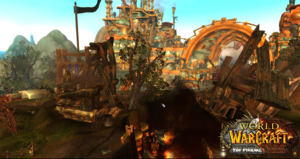
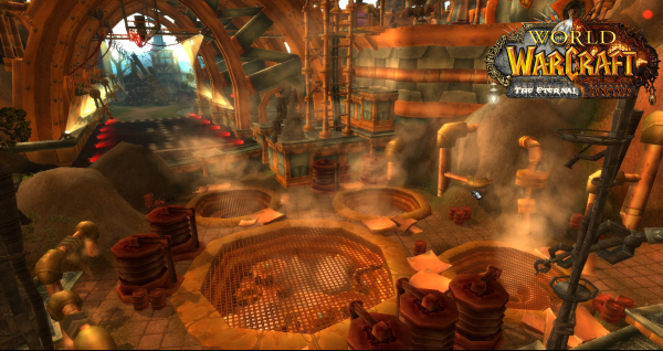 Maybe in the future I will release these files. It is not a model here. It is a set of custom and original models lego builded together in Noggit. The archway for the hangar is custom along with the catwalks.
 -
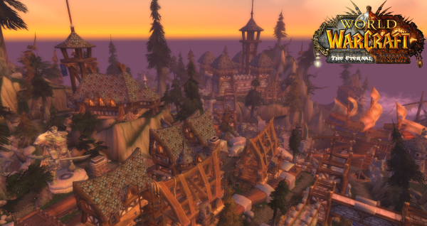
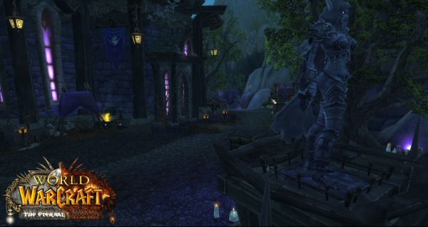
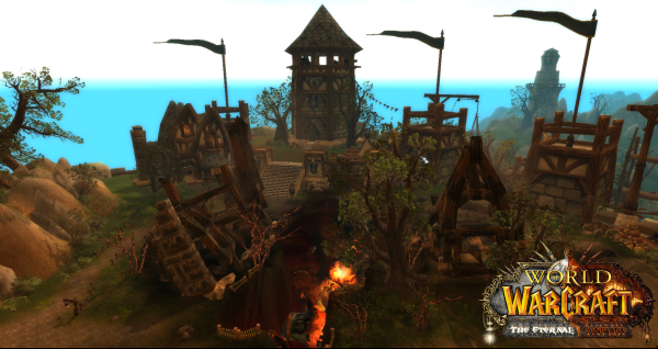
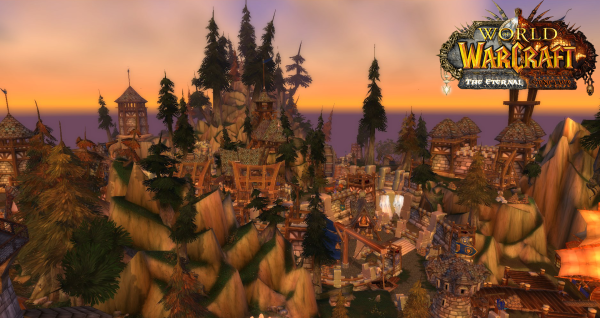
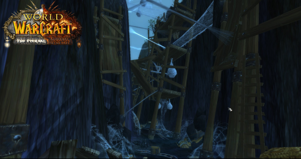
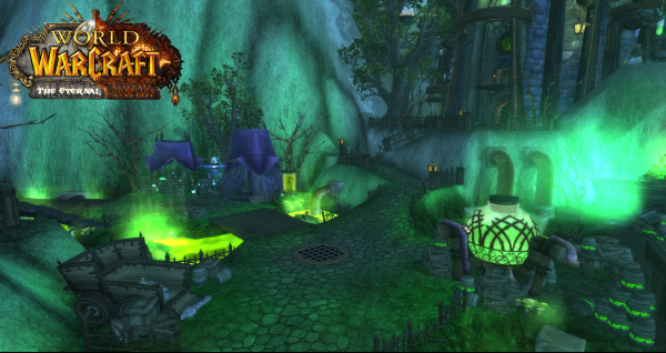
From the album: The Eternal Conflict (2014-2016, abandoned)
-
The Eternal Conflict (2014-2016, abandoned)
Images added to a gallery album owned by Skarn in Member Albums
This is a project I used to work on 5 years ago. It was abandoned due to a hard time using old tools that existed at a time. Level design is mostly done by me, models by @Balkronand @Kadzhamit. The zones were WIP and never got finished, posting mainly for archive purposes. -
-
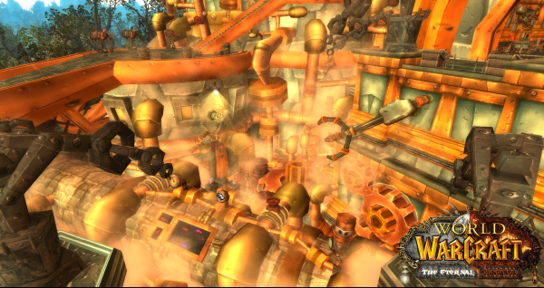
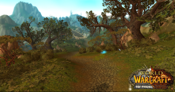
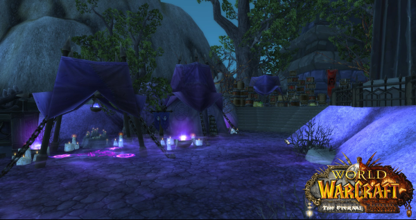
From the album: The Eternal Conflict (2014-2016, abandoned)
-
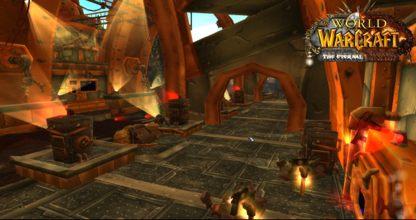
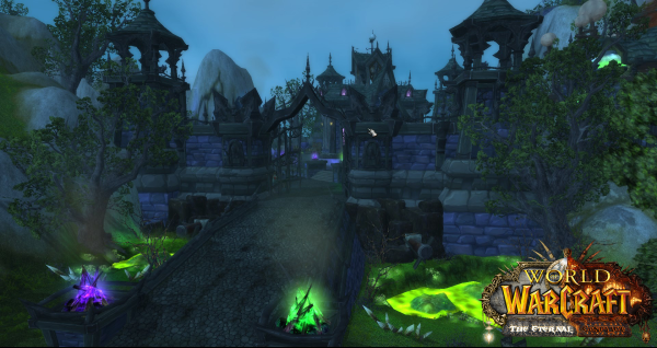
From the album: The Eternal Conflict (2014-2016, abandoned)
-
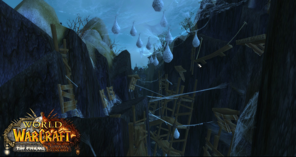
From the album: The Eternal Conflict (2014-2016, abandoned)
-
From the album: The Eternal Conflict (2014-2016, abandoned)